


|
NL5: circuit simulator you can trust This is quite strong and ambitious statement. First reaction of any engineer working with circuit simulators is predictable and obvious: why would anybody trust … what’s its name, NL5? And what about my favorite (name one)? The truth is: every simulator may easily produce inaccurate or even absolutely wrong results. Sometimes wrong results can be easily recognized just by looking at weird waveforms. But, unfortunately, very often wrong results will look credible even for experienced engineers. This happens for various reasons, and, in fact, both user and simulator contribute into it. While user’s contribution can be minimized by education, experience, and common sense, simulators can still do things you’ll never even guess. Sometimes this is caused by flaws of the simulation algorithm, but very often it is done intentionally, without notifying the users. NL5 was originally designed to minimize any erroneous contribution of the simulation algorithm to simulation results. Thanks to the feedback from many active users, NL5 algorithm is now capable of dealing with practically any circuit. If something goes wrong, most likely this is user’s fault: typos in component parameters, missing wires or connections, or maybe just wrong circuit idea. What would circuit simulator provide wrong results? That’s what you will learn in the next chapter. What’s wrong with my circuit simulator (not NL5)? Every engineer asks this from time to time when looking at weird simulation results. Or even not getting any results at all. The schematic is checked again and again, even the prototype is already working, but the simulation gives something clearly wrong. Why? Relax: most likely, there is nothing wrong with the simulator, and your circuit is also correct. What might be wrong is your expectations: this particular simulator may not be the right tool for your task. Unfortunately, simulators don’t say "sorry, I can’t do that". It’s entirely your responsibility to understand the limitations of the simulator and select one you can trust. Here are a few typical situations when you should be alerted to potential simulation problems. 1. Most circuit simulators are designed and optimized to deal with "real" electronic parts. It might sound strange, but very simply components with just basic behavior (for example, "ideal" diodes and switches) could be a real trouble for practically all simulators. 2. Simulators also prefer "real" circuit topology and "reasonable" component parameters. If you are inventing something new, you might want to go beyond capabilities of current technology, which could be very problematic. 3. When using manufacturers SPICE models, be aware that not all of them can be trusted, especially at the extremes of the spec, for example very high frequencies. Not all simulators are "transparent" enough to allow you modifying the model in a way you’d like it. 4. Some very simple schematics may be challenging for simulators for different reasons. Simulators don’t give up easily, and they will do various tricks to make simulation work. For example, adding some small/large resistors or capacitors can help improve convergence at switching points. Unfortunately, this can lead to side effects: simulation results may be not what you expect. And what is worse, these "tricks" are often hidden and not communicated to the user. As a result, you may spend a lot of time trying to understand why the simulation results do not represent the actual circuit behavior. What is special about NL5 and why it might work better for you? That’s what you will learn in the next chapters. NL5 approach is different or even opposite to traditional, mostly SPICE-based, simulators. The main idea is to start with a very simple circuit representation, and then add the desired complexity step by step, always keeping the simulation results valid and reliable.  1. The initial design, or "proof of concept", provides an understanding of whether the design idea is feasible at all, how exactly it works, and what performance can be achieved. This is done mostly with "ideal" parts: extremely simple components with just basic functionality and a minimum number of parameters used. Some examples of "ideal" components are "ideal" diodes and switches (zero/infinite resistance, instantaneous switching). The use of such components results in very reliable simulation: getting wrong simulation results is very unlikely. 2. The next step is adding complexity: using components with more "realistic" behavior rather than "ideal". You can add parasitic capacitance and inductance, leakage, offsets, on/off resistance, limited gain and bandwidth, etc. Components and parameters can be modified not all at once, but step by step, one at a time. This will help to separate the impact of each item on the functionality and performance and determine which are the most critical and should be taken care of in real hardware. 3. A similar approach can also be used for verification and troubleshooting of existing working products. By first using simple "ideal" components, and then adding "real" functionality step by step, you will be able to determine what is actually causing problems in the real hardware. The use of simple "ideal" components results in robust and reliable simulation that can be trusted. Because the functionality of simple components is well known, simulation results can be easily verified by simply inspecting simulation data points. With NL5, potential design problems can be identified and fixed much more easier than with simulators using "real" models and complex simulation methods. The basic components used in NL5 are extremely simple: pure resistor, capacitor, inductor, voltage/current source, etc. These components do not have any "parasitics" or hidden parameters that some simulators add, sometimes even without notice. All parameters of the NL5 components are visible and can be changed by the user. A unique capability of NL5 is that practically any component parameter can be set to any value, including negative, zero, and even infinite. This allows to create a component that does not exist in real life, so it can be called "ideal". Typical examples of "ideal" components are a switch and diode with zero and infinite resistance, an amplifier with infinite gain and bandwidth: 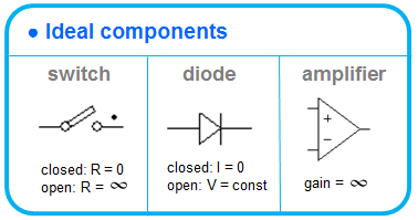 Although such "ideal" components do not exist in real life, their use in simulation is very advantageous for many reasons. Components with complex and special functionality are created using basic "ideal" components. For example, a limited bandwidth, limited output voltage amplifier consists of a resistor, a capacitor, controlled voltage sources, and ideal diodes: 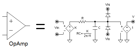 The equivalent circuit of such components can be found in the NL5 Help and "NL5 Reference" document. NL5 performs simulation with linear components only. The characteristic of the non-linear component can presented as piecewise linear (PWL): 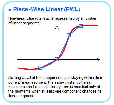 It can be a very simple characteristic with just two linear segments: for example, an ideal diode could be either short circuit (zero resistance) or open circuit (infinite resistance). A more complex PWL characteristic can be defined using a custom look-up table with as many linear segments as needed: 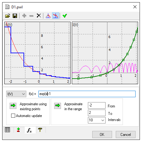 And finally, there is a group of "function" type components: digital logic, function, C-code, DLL, and more. These components accept input signals and produce output signals as a function of input signals. It is important to know that produced signals are applied to the outputs on the next simulation step. This is equivalent to a delay of one simulation step, which is typically very small, but can still affect functionality of closed loop systems. Using simple "ideal" components can seem like a big advantage: the simpler the components, the simple the simulation algorithm could be. However, this is not always the case. For example, a quite common situation with "ideal" switches is when capacitor is being instantly recharged through a switch with zero resistance, which results in infinitely short current of infinite amplitude: the Dirac pulse, or delta-function. Handling this properly is not an easy task. The problem here is mainly not how to calculate the final voltages after switching, but how to present possible infinite signals to the user. In NL5, such situations are taken care of by the "instantaneous switching" algorithm, and here is how it works. 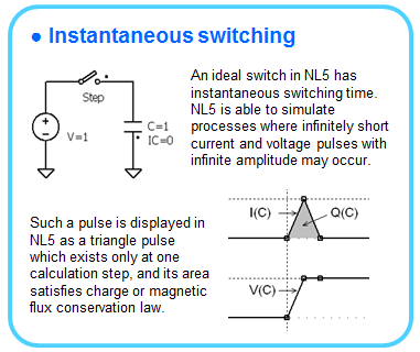 Although the amplitude of the current pulse is infinite, its area (integral over time) is limited and equal to the change of capacitor charge during switching. It is this charge, and not infinite amplitude, that actually could be of interest to an engineer, and should be displayed on the transient graph in some clear and logical way. In NL5, such a pulse is shown as a symmetrical triangular pulse with the duration of each slope equal to the minimal calculation step used at that moment, and the area satisfies charge conservation law. If the minimal simulation step is the same at the moments when such pulses occur, the charge transferred through the switch can be easily compared visually, just looking at the graph. Similarly to infinite current pulse through a capacitor, disconnecting current through an inductor with an infinite resistance switch can produce an infinite voltage spike across the inductor. Such spike will be displayed in exactly the same way, and the area of the spike will satisfy magnetic flux conservation law. At first glance, NL5 simulation algorithm looks very simple and straightforward. However, it took years to make it truly robust and trustable. Here is the main idea behind it. When simulation starts at t=0, a Direct Current (DC) operating point is calculated. At this point, some components can have Initial Condition (IC) specified (capacitor voltage, inductor current), but this is not required. Once the DC operating point is found, the actual transient simulation begins. At any moment, the circuit operates in "linear range", which means it can be described by a system of simple linear differential equations. As long as all components maintain their state and stay within their current linear segment, the system does not change and can be easily solved. While the circuit is in linear range, the algorithm continuously performs "switching point detection": it checks for conditions on all components that may change their state or linear segment. When at least one component reaches the switching point, the algorithm performs "instantaneous switching", recalculates the system, and continues simulation in the new linear range. 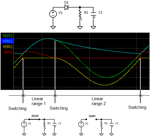 The system of differential equations is solved by the second order trapezoidal integration method, which provides sufficient accuracy with good robustness and simulation speed. This method is very simple and transparent, so that the simulation results can be trusted or, if needed, easily verified just by inspecting the data points. 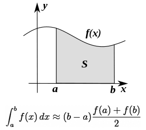 An important part of the algorithm, which determines the accuracy of the results and sometimes affects the convergence of the switching process, is simulation step. Typically, the user only specifies the maximum step, and simulator can decrease the step when needed to achieve the required accuracy. Such approach is highly questionable for many reasons., For example, if the circuit has a wide range of voltages and currents in different nodes and brunches, it does not make much sense to set the same absolute accuracy for all of them. Also, specifying relative accuracy is meaningless for signals equal or close to zero. NL5 approach to setting simulation step is quite simple: "You are the boss". The user sets the “maximum simulation step” based on knowledge or expectation of the circuit time constants, desired accuracy, simulation speed, etc. NL5 can be allowed (by the user) to decrease the step automatically only for three reasons: to follow fast changing signal source waveforms, to accurately detect switching points, and to provide reliable convergence of switching process. 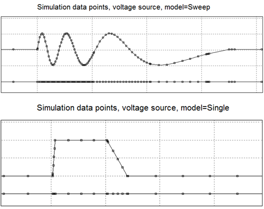 Such a responsibility might look like unnecessary "burden". However, it also has a bright side: when selecting a step value, the user has a good chance to better understand circuit operation, predict possible limitations, find out critical points and requirements for frequency characteristics and delays of the parts used. NL5 DLL is a dynamic-linked library (DLL), available for Windows, Linux, and macOS. NL5 DLL is included into NL5 Circuit Simulator package. It performs transient simulation and AC analysis of circuits created by NL5 Circuit Simulator. NL5 DLL can be used as an analog simulator which is started and controlled from other applications and tools (MATLAB, Python, custom C/C++ code): 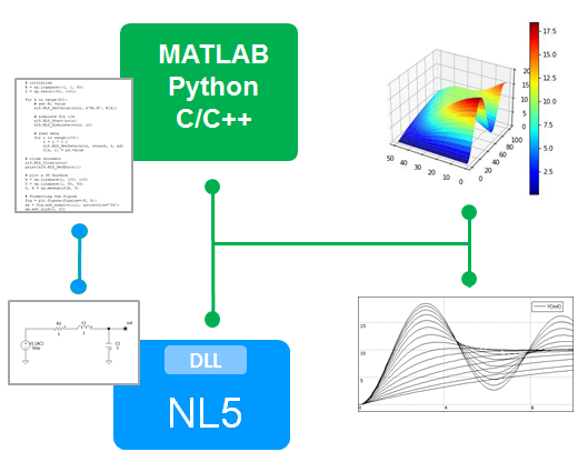 It can also serve as an analog co-simulation tool working with digital simulation tools (for example SystemVerilog simulators through DPI interface): 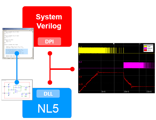 NL5 perfectly fits needs of all users, regardless of their experience, interests and expectations. NL5 is ideal for novices and students studying electronics. The learning curve is negligible: basic experience with Windows applications is all it takes to get started with NL5. The user-friendly and intuitive interface allows for quick modifying of the schematic, providing instant answers to the "what if …?" questions. Experienced engineers can simulate rather large systems taking advantage of extremely fast and robust algorithm, since the convergence problem inherent to SPICE is no longer an issue. A powerful scripting language and HTTP link allow the user to perform complex tasks with NL5 GUI version, as well as using it as "add-on" simulation engine with popular engineering tools such as MATLAB, Python, System Verilog. Although NL5 was originally designed for simulating switching power supplies, it has proved to be an excellent simulation tool for almost any type of electronic circuitry: from nanoseconds transmission lines and high power RF generators to precision instrumentation and digital signal processing. Due to the very basic nature of ideal components used in NL5, its application area is not limited to electronics. It can be successfully used for systems simulation by researchers in many disciplines, such as mechanics, heat transfer, fluid dynamics, to name a few. NL - simple introduction to NL5 NL is a free introductory version of NL5 Circuit Simulator (as well as all previous and future generations of “Non-Linear” circuit simulation tools). It uses the same simulation algorithm as NL5, same component types and models, and it can perform simulation with unlimited number of components. However, its user interface is very simple and limited, and it does not support most of the features, tools, and unique functionality available in NL5. It also supports just a small number of component types and models offered by NL5. NL can be used to learn how schematic is entered and edited, how component parameters are specified; then you can perform simulation and see results in a very simple format. You can continue using NL for simple projects that do not require special components, extensive analysis and tools: this should be quite adequate tool for beginners, students, and amateurs. Simulate your future design now Here is a summary of what you’ve learned from previous chapters about NL5: - NL5 uses very simple "ideal" linear components;- non-linear components are presented as piecewise linear (PWL); - complex components are created from basic “ideal” components; - practically any component parameters can be set to any value; - NL5 can handle any, even "unrealizable" circuit topology. When testing an existing design, NL5 allows to start with a very simple circuit representation and then add the desired complexity and parasitics step by step, always providing valid and reliable simulation results. This makes it easy to reproduce operation of real hardware and determine which components and parameters are causing problems and not working as expected. NL5 is an "ideal" tool for testing new design ideas. You can iterate a design very fast (literally, as soon as a new idea comes to your mind), get a good understanding of how it should work, prove its feasibility, discover limitations. NL5 can simulate any, even "unrealizable" circuit topology, with arbitrary component parameters, in any time/frequency/voltage/current range. In other words, you can simulate "a circuit that does not exist" and probably can’t be built at all with current components and technology. Your new design may look "crazy" or even "stupid" today, but could become reality tomorrow. And you are ready for it. With NL5. NL5 ist der nichtlineare electronische Schaltungssimulator. Die erste Version für PCs entstand in den frühen 90ziger Jahren zur Entwicklung von Schaltnetzteilen. Später wurde es zu NL4 für Microsoft Windows® überarbeitet, das für beinahe zehn Jahre große Verbreitung unter Experten auf verschiedenen Gebieten der Elektronik fand. NL5 ist die erste offizielle Vertriebsversion von NL4. Im Unterschied zum konventionellen SPICE-Simulator, der vorgibt eine genaue Simulation von elektronischen Schaltungen mit Hilfe von komplexen und detaillierten nichtlinearen Modellen der elektronischen Komponenten mit Dutzenden von Parametern durchzuführen, geht NL5 dagegen ganz anders vor. Zum Ersten, NL5 verwendet, wenn immer möglich, ideale Komponenten. Eine ideale Komponente liefert nur die für die Komponente ihres Typs erforderliche wesentliche Funktionalität. In der Regel sind diese Komponenten sehr einfach und benötigen nur eine minimale Anzahl von Parametern. Das Resultat ist, daß ihr Verhalten klar und vorhersehbar ist. Zum Beispiel hat ein idealer Schalter keinen Widerstand, wenn er geschlossen ist, einen unendlichen Widerstand, wenn er geöffnet ist und er schaltet unmittelbar ohne jegliche Verzögerung. Für solch einen Schalter benötigt man keinerlei Parameter. Zum Zweiten, nichtlineare Komponenten (d.h. Dioden, Transistoren oder Verstärker) werden als teilweise lineare (piecewise linear - PWL) Komponenten dargestellt, die eine Anzahl von linearen Segmenten enthalten. Im Falle einer einfachen Diode, die entweder geöffnet oder geschlossen ist, benötigt man lediglich zwei Segmente zur Darstellung des PWL. So lange wie alle Komponenten in ihrem gegenwärtigen linearen Segment verbleiben, kann dasselbe System linearer Gleichungen verwendet werden. Das System linearer Gleichungen muss nur zu dem Zeitpunkt modifiziert werden, wenn eine der Schaltungskomponenten ihr lineares Segment ändert. Das kann sehr viel schneller getan werden, als das Lösen von komplexen nichtlinearen Gleichungen für jeden Zeitpunkt der Simulation, was SPICE-Simulatoren normalerweise tun. Das Verständnis dieser NL5-Prinzipien gibt dem Anwender die volle Kontrolle über den Simulationsprozess. Die Verwendung idealer Komponenten mit einfachen PWL-Modellen führt zu einer extrem schnellen Simulation und der unmittelbaren Verifizierung der Schaltungsfunktionen. Andererseits, genauere Ergebnisse können erreicht werden durch die Identifizierung kritischer Schaltungskomponenten (Solche, die die Schaltungsfunktion am meisten beeinflussen.) und die Verwendung komplexerer Modelle für diese Komponenten. So kann der Anwender eine zweckentsprechende Balance zwischen Geschwindigkeit und Genauigkeit erreichen. NL5's Hauptvorteil ist die Fähigkeit zu Iterationen der Schaltung und zur sehr schnellen Simulation. Das ist besonders wichtig, wenn in den frühen Stadien des Projektes durch Verwendung von idealen Komponenten und einfachen Modellen das allgemeine Konzept und dessen Realisierbarkeit schnell getestestet werden müssen. Danach kann eine tiefere Analyse unter Verwendung von genaueren Modellen und vergrößerter Komplexität der kritischen Komponenten durchgeführt werden. Ungeachtet dessen, daß NL5 vorwiegend zur Simulation von Schaltnetzteilen entwickelt wurde, hat es sich als Anwendungsprogramm für fast jede Art elektronischer Schaltungen behauptet, von Nanosekunden-Übertragungleitungen und HF-Leistungsgeneratoren zu Präzisionsmessschaltungen und DSP-Anwendungen. Frequenz-Domain-Analyse und einige zusätzliche sehr spezielle Merkmale erweitern das Anwendungsspektrum dieses Programms. Es stellt dem Ingenieur so gut wie alles zur Verfügung, was er in seiner produktiven Arbeit braucht. NL5 erfüllt die Anforderungen aller Anwender unabhöngig von deren Erfahrung, Interessen und Erwartungen. NL5 ist ideal für Anfänger und Elektronikstudenten. Die Anlernphase ist vernachlässigbar kurz. Grundlagenwissen des Windows® OS ist alles, was man braucht, um mit NL5 zu starten. Ein anwenderfreundliches und intuitives Interface erlaubt eine schnelle Modifizierung der Schaltung und sogar „Editieren im Fluge“ während der Simulator arbeitet. Das erlaubt die unmittelbare und schnelle Beantwortung der Frage „Was ist wenn...?“ Durch den Vorteil des sehr schnellen und robusten Algorithmus, der frei von Konvergenzproblemen ist, wie sie von SPICE her bekannt sind, können erfahrene Ingenieure relativ große Systeme simulieren. Eine einfache, aber leistungsfähige Skriptsprache ermöglicht dem Anwender die Verwendung von sehr komplexen Simulationsabläufen durch die Kopplung des NL5 „Add-On“ mit populären Anwendungsprogrammen, wie zum Beispiel MATLAB® und anderen. Die sehr einfache Natur der idealen Komponenten, die NL5 verwendet , erlaubt Anwendungen nicht nur in der Elektronik. NL5 kann auch erfolgreich zur Simulation von Systemen auf vielen verschiedenen Gebieten, wie zum Beispiel der Mechanik, Thermodynamik und Hydraulik, um nur einige zu nennen, verwendet werden. Please see English NL5 es el Simulador de Circuitos Electrónicos No Lineales. La primer versión de NL para computadoras personales fue desarrollado a comienzos de los '90 como una herramienta para el diseño de fuentes de alimentación conmutadas. Desde entonces, NL ha evolucionado en el NL4 bajo Microsoft Windows®, el cual ha sido extensivamente empleado por ingenieros destacados en diferentes areas de la electrónica por casi 10 años. NL5 es la primera versión disponible públicamente. A diferencia de los simuladores convencionales basados en SPICE, los cuales intentan realizar simulaciones precisas de circuitos electrónicos usando complejos y detallados modelos no lineales de componentes con docenas de parámetros, el enfoque de NL5 es sustancialmente diferente. Primeramente, NL5 trata con componentes ideales en la medida de lo posible. Un componente ideal es aquel que provee sólo la funcionalidad básica requerida para un componente de ese tipo. Como regla general, éste es muy simple y descripto por un mínimo número de parámetros. En consecuencia, su comportamiento es claro y muy predecible. Por ejemplo, una llave ideal posee resistencia nula cuando está cerrada, resistencia infinita cuando está abierta y conmuta instantáneamente. Para tal llave no se requiere parámetro alguno. En segundo lugar, componentes alineales (por ejemplo, diodos, transistores o amplificadores) se representan por un modelo lineal por tramos (PWL), consistente en cierto número de segmentos lineales. Por ejemplo, un simple diodo puede estar abierto o cerrado, de modo que su representación PWL consiste en sólo dos segmentos. En la medida en que todos los componentes permanezcan dentro del segmento lineal actual se puede emplear el mismo sistema de equaciones lineales. Esto puede siempre resolverse mucho más rápido que ecuaciones no lineales complejas prácticamente en cada paso de la simulación, lo cual es lo que usualmente hacen simuladores basados en SPICE. Entender estos principios sobre NL5 proporciona a los usuarios un control completo del proceso de simulación. Usar componentes ideales con modelos PWL sencillos conduce a una simulación extremadamente veloz y proporciona una idea de la funcionalidad circuital muy rápidamente. Por otro lado, se pueden obtener resultados más precisos identificando componentes críticos (aquellos que más afectan las prestaciones del circuito) y usando modelos más complejos para dichos componentes. De este modo, los usuarios pueden siempre intercambiar razonablemente entre velocidad de simulación y el nivel deseado de exactitud. La mayor ventaja de NL5 es su habilidad para efectuar iteraciones sobre el diagrama circuital y realizar simulaciones extremadamente rápidas. Esto es especialmente importante en las etapas tempranas de un proyecto, en las que empleando componentes ideales y modelos sencillos, los ingenieros pueden evaluar un concepto general y demostrar la factibilidad del diseño muy rápidamente. Luego de eso, puede realizarse un análisis más profundo aplicando modelos más exactos y agregando una complejidad razonable a los componentes críticos. A pesar de haber sido originalmente diseñado para simular fuentes conmutadas, NL5 ha demostrado ser una excelente herramienta de simulación para casi cualquier tipo de circuito electrónico, desde lineas de transmisión de nanosegundos y generadores de RF de alta potencia hasta instrumentación de precisión y procesamiento digital de señales. Recientemente agregados, el análisis en el dominio frecuencial y algunas características bastante particulares, amplían el horizonte de NL5 ofreciendo a los ingenieros prácticamente todo lo que ellos podrían necesitar en producción. NL5 cumple perfectamente con las necesidades de todos los usuarios independientemente de su experiencia, intereses y expectativas. NL5 es ideal para novicios y estudiantes de electrónica. La curva de aprendizaje es muy corta: un conocimiento básico del sistema operativo Windows es todo lo que se requiere para comenzar a usar NL5. Una interface amigable e intuitiva permite una rápida modificación del esquema circuital, aún editando simultáneamente mientras se ejecuta la simulación, suministrando respuestas instantáneas a preguntas "¿qué ocurre si...?". Los ingenieros experimentados pueden simular grandes sistemas, aprovechando el algoritmo extremadamente rápido y robusto, dado que los problemas de convergencia inherentes a SPICE no representan un obstáculo. Un poderoso y simple lenguaje de codificación permite al usuario realizar tareas complejas ejecutando NL5 como el motor accesorio de simulación de otras herramientas populares de ingeniería tales como MatLab y otros. Debido a la naturaleza muy básica de los componentes ideales usados en NL5, su area de aplicación no se limita a la electrónica. Puede ser usado exitosamente para simulación de sistemas por investigadores de muchas disciplinas tales como mecánica, termodinámica, dinámica de fluidos, por mencionar algunas. Please see English NL5 est un simulateur de circuits électroniques non linéaires. La première version de NL pour les ordinateurs personnels fût développée dans les années 90, en tant qu'outil de conception pour les alimentations à découpage. Depuis, NL a évolué pour devenir NL4 et s'accommoder de systèmes d'exploitation tels que Microsoft Windows®. NL4 a été largement utilisé par des ingénieurs de renommée mondiale dans différents domaines de l'électronique pendant près de 10 ans. NL5 est la première version à être disponible pour toutes et tous. Contrairement aux simulateurs SPICE traditionnels (qui utilisent des descriptions complexes et détaillées de modèles de composants linéaires), l'approche NL5 est différente. Tout d'abord, NL5 utilise des composants idéaux autant que faire se peut. Un composant idéal est un élément qui fournit seulement la fonction de base recherchée : un interrupteur à pertes nulles pour ouvrir un circuit par exemple, une diode sans seuil pour n'autoriser le passage du courant que dans un sens etc. En règle générale, ce modèle est très simple et décrit par un nombre minimal de paramètres et d'équations. Par conséquent, son comportement est clair et prévisible. Dans le cas de l'interrupteur susdit, il offrira une résistance nulle lorsqu'il est fermé, et une résistance infinie en position ouvert. Passer d'un état à l'autre s'effectue instantanément. Pour un tel interrupteur, nul besoin de paramètres ! Deuxièmement, les éléments non linéaires (par exemple les diodes, les transistors, ou encore les amplificateurs) sont découpés en tranche de segments linéaires. Ce mode d'étude se nomme Piece Wise Linear (PWL) en Anglais. Ainsi, si une simple diode est ouverte ou fermée, sa représentation PWL comprend uniquement deux segments. Chacun de ces segments est régi par des jeux d'équations linéaires. Le système n'est modifié que lors d'un changement d'état. Ainsi, un simulateur tel NL5 ne résout des équations non linéaires que lors de la discontinuité d'un segment (une transition) et non pas à pas, comme avec SPICE. Le temps de simulation en est grandement amélioré et les erreurs de convergence quasiment éliminées. La compréhension de ces principes donne aux utilisateurs de NL5 le contrôle total du processus de simulation. La mise en œuvre de composants idéaux couplés à la méthode PWL engendre une simulation extrêmement rapide, et donne très rapidement une idée générale de la fonctionnalité du circuit. D'autre part, des résultats plus précis peuvent être obtenus en identifiant les composants critiques (ceux qui affectent les performances du circuit), et en les remplaçant par des sous-circuits plus complexes afin d'affiner l'analyse. Ainsi, les utilisateurs peuvent-ils toujours choisir entre la vitesse de simulation et le niveau de précision désiré. L'avantage majeur de NL5 réside dans sa capacité à effectuer des itérations à partir du schéma pour lancer ensuite une simulation extrêmement rapide et apprécier immédiatement les résultats obtenus. Ceci s'avère particulièrement utile lors de l'exploration d'un projet, quand, en utilisant des composants idéaux et des modèles simples, les ingénieurs peuvent évaluer un concept général et prouver sa faisabilité en peu de temps. Après cette étape de premier ordre, une analyse approfondie peut être effectuée en sélectionnant des modèles plus précis et en augmentant raisonnablement la complexité des sous-circuits critiques. En dépit d'une conception originale guidée par la nécessité d'étudier des alimentations à découpage, NL5 se révèle un excellent outil de simulation pour une large palette de circuits électroniques, de lignes de transmission aux temps de propagation de quelques nanosecondes, à de fortes puissances radiofréquences, en passant par l'instrumentation de précision et le traitement de signal numérique. Récemment ajoutée, l'analyse fréquentielle de circuits à découpage, associée à certaines caractéristiques uniques, élargit naturellement les possibilités d'utilisation de NL5, offrant aux ingénieurs presque tous les outils nécessaires pour un travail productif. NL5 s'adapte parfaitement aux besoins de tous les utilisateurs, quelle que soit leur expérience, leurs intérêts et attentes. NL5 est idéal pour les novices et les étudiants qui étudient l'électronique. La courbe d'apprentissage est faible à court terme : la connaissance de base du système d'exploitation Windows® est la seule connaissance nécessaire afin de commencer à travailler avec NL5. Une interface conviviale et intuitive permet une modification rapide du schéma, même lorsque que la simulation est en cours d'exécution, donnant ainsi instantanément une réponse aux expérimentations et essais en cours. Les ingénieurs expérimentés peuvent simuler de gros systèmes, profitant de l'algorithme extrêmement rapide et robuste. Comme expliqué auparavant, en absence de résolution pas à pas d'équations non-linéaires, les problèmes de convergence inhérents à SPICE ne représentent plus d'obstacle. Un langage de script simple et puissance permet à l'utilisateur d'assigner des tâches complexes à NL5, en l'utilisant comme ajout de moteur de simulation lors de l'utilisation d'outils d'ingénierie tels que MATLAB® et autres logiciels scientifiques. En raison de la nature même des composants utilisés dans NL5, son domaine d'application ne se limite pas à l'électronique. Il peut être utilisé avec succès pour la simulation de systèmes par des chercheurs évoluant dans des disciplines variées, telles la mécanique, la thermodynamique et la mécanique des fluides, pour n'en citer que quelques unes. Please see English NL5 är icke-linjär elektronisk krets Simulator. Den första versionen av NL för personda-torer utvecklades i början'90s som ett verktyg för att byta nätaggregat design. Sedan dess NL har utvecklats i Microsoft Windows®-baserade NL4, som har används i stor ut-sträckning av världen klassens ingenjörer på olika områden inom elektronik för nästan 10 år. NL5 är den första version skall vara offentligt tillgänglig. Till skillnad från konventionella SPICE-baserade simulatorer, som låtsas att utföra exakt simulering av elektroniska kretsar som använder komplexa och detaljerade icke-linjär komponent modeller med massor av parametrar, de NL5 synsätt är helt annorlunda. Först NL5 behandlar ideala komponenter så mycket som möjligt. En idealisk komponent är en som ger bara en grundläggande funktionalitet som krävs för komponent av denna typ. Som regel är det mycket enkel och beskrivs med ett minimalt antal parametrar. Som ett resultat av dess beteende är tydlig och förutsägbar. Till exempel, ett ideal växlar har noll motstånd när de är stängda, oändligt motstånd när de är öppna, och det är att byta direkt. För att en sådan växla några parametrar krävs alls. Andra, icke-linjära komponenter (t.ex. dioder, transistorer, eller förstärkare) är represen-terade som piecewise linjära (PWL): består av ett antal linjära segment. Exempelvis en enkel diod är antingen öppna eller stängda, så att dess PWL representation består av bara två segment. Så länge alla komponenter vistas inom deras nuvarande linjära segment, samma system av linjära ekvationer kan användas. Systemet ändras bara på stunder då minst en komponent byter linjära segment. Det kan alltid ske mycket snabbare än att lösa komplexa icke-linjära ekvationer vid nästan varje steg i simuleringen, vilket är vad SPICE-baserade simulatorer brukar göra. Att förstå dessa NL5 principer ger användaren full kontroll över simuleringen process. Använda ideala komponenter med enkel PWL modeller resulterar i en extremt snabb simulering, och ger en allmän uppfattning om krets funktionalitet mycket snabbt. Å andra sidan mer rättvisande resultat kan uppnås genom att identifiera kritiska komponenterna (som påverkar krets prestanda mest), och med hjälp av mer komplicerade modeller för dessa komponenter. Därmed kan användarna alltid göra en rimlig avvägning mellan simulering hastighet och önskad nivå av noggrannhet. NL5 stora fördel är dess förmåga att göra iterationer av den schematiska och utföra en simulering oerhört snabbt. Detta är särskilt viktigt i tidiga skeden av ett projekt, då med hjälp av ideala komponenter och enkla modeller, tekniker kan utvärdera ett allmänt be-grepp och bevisa genomförbarheten av formgivningen mycket snabbt. Efter att en grun-dlig analys kan utföras genom att använda mer precisa modeller och lägger till rimliga komplexitet till kritiska komponenter. Trots att ursprungligen utformad för simulering av switchade strömkällor, NL5 har visat sig vara ett utmärkt simulering verktyg för nästan alla typer av elektroniska kretsar, från nanosekunder överföringsledningar och hög effekt RF generatorer, till precision instru-mentering och digital signalbehandling. Nyligen inlagda frekvensdomänberäkning analys och en del helt unika egenskaper bredda NL5's horisont erbjuder ingenjörer nästan alla de skulle behöva för produktivt arbete. NL5 perfekt passar behoven hos alla användare, oberoende av deras erfarenheter, intres-sen och förväntningar. NL5 är idealisk för nybörjare och studenter elektronik. Inlärningskurvan är obetydligt kort: grundläggande kunskaper om Windows operativsystem är allt som behövs för att börja arbeta med NL5. En vänlig och intuitivt gränssnitt tillåter snabb ändring av den schematiska även "on-the-fly" redigering medan simuleringen är igång, vilket ger svar på "vad händer om ...?" Frågor. Erfarna ingenjörer kan simulera ganska stort system, med fördel för extremt snabb och robust algoritm, eftersom konvergensen problem som hänger samman med SPICE är inte längre en fråga. En enkel, men kraftfull, skriptspråk tillåter användaren att utföra kom-plicerade uppgifter köra NL5 som "add-on" simulering motor med populära tekniska verktyg som MATLAB och andra. På grund av den mycket grundläggande karaktär ideala komponenter som används i NL5, dess användningsområde är inte begränsat till elektronik. Det kan med framgång använ-das för system för simulering av forskare inom många discipliner, såsom mekanik, ter-modynamik, fluiddynamik, för att nämna några. Please see English NL5は理想的素子と区分的線形コンポーネントを扱うアナログ電子回路シミュレータです。パソコン用NLシミュレータの最初のバージョンは、スイッチング電源設計のためのツールとして1990年代前半に開発されました。それ以来、ほぼ15年間、NLはMicrosoftWindows®ベースのツールへ進化し、電子機器の様々な分野で世界トップクラスの技術者によって広く使用されています。最初の利用可能なバージョンのNL5は2009年にリリースされました。 従来のSPICEベースのシミュレータは、数十のパラメータを持つ非線形成分の"real"なモデルを用いた正確なシミュレーションを実行させようとしますが、NL5は逆のアプローチを採用しています。複雑なモデルの代わりに非常に単純な "ideal" (理想)コンポーネントを提供しています。 "理想”コンポーネントは、そのタイプのコンポーネントに必要な基本的機能なだけを提供するものです。理想コンポーネントは非常に単純で、最小限のパラメータ、または全くないパラメータ(例えば、理想的なスイッチ)で記述されます。結果的に、引き起こされる潜在的な問題を数値アルゴリズムによって容易に検出できるようになり、その動作は明確かつ予測可能なものになります。 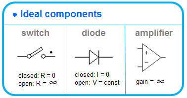 もう一つの重要なNL5の機能は理想的なスイッチとダイオードを瞬時に切り替える 能力です。 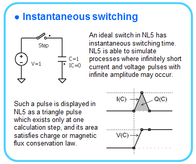 精密な"リアルな"非線形モデルの代わりに、NL5は、区分線形 (PWL)モデルを使用します。PWLモデルを用いたシミュレーションは、シミュレーションのほとんど全てのステップで複雑な非線形方程式を解くよりもはるかに高速に行うことができます。 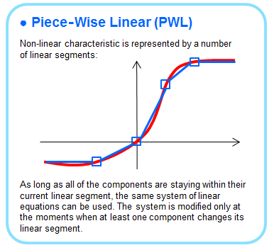 回路シミュレーションにおいて"理想的"コンポーネントを使用することは多くの利点があります。 "リアルな"部品が使用されている場合、それぞれがシステムの方程式に多く"変数"を追加します。: 寄生容量、寄生インダクタンス、漏れ電流、オフセット、オン/オフ抵抗、制限される利得と帯域幅等です。これらすべてがシミュレーションプロセスにおいて考慮され、非常に複雑に、遅くなり、信頼性が低くなります。
「理想的」コンポーネントを使用し、「瞬間的なスイッチング」機能を加えシミュレーションタスクをかなり簡素化します。
初期のプロジェクトの段階で、新しい回路アイデア、新しいトポロジー、またはデザインコンセプトを評価するために"理想的"コンポーネントで行うシミュレーションが特に便利で効果的です。それは "実際の"数百のパラメータの複雑な影響受けずに、回路の一般的な動作を明確に理解することができます。
デザインコンセプトを"理想的"コンポーネントで承認した後、重要なコンポーネントに合理的な複雑さを追加する、または標準的なSPICEベースのツールで分析を続けることによって徹底した詳細なシミュレーションを継続して行うことができます。 単純なコンポーネントを扱うことは非常に簡単な作業なので、なぜSPICEでは「理想」コンポーネントを使用しないのでしょうか?と思うかもしれません。残念ながら、それは可能でありません。 SPICEアルゴリズムは、最初に"実際"の集積回路の正確なシミュレーションを実行するように設計され、それは非常によくできてました。しかし、「理想的」コンポーネントは"現実"の世界には存在しない特定の動作状況を引き起こす場合があります。少し例を挙げれば、フローティングノード、電圧ループ、電流カットセット等です。標準のSPICEアルゴリズムは固有の限界があり、それが動作すると状況に対応するのを防いでしまいます。 NL5は"理想的"なシミュレーションのために設計されているので、容易にこのような"厄介な"状況を処理してしまいます。
SPICEのアルゴリズムは非常に複雑な回路の高速で正確なシミュレーションを提供することができますが、時には、正しい動作させるため、または単に動作させるためにかなりの努力を要し、徹底的に選択する必要がある(ステップ、許容差、等)数十のシミュレーションパラメータがあります。それには、多くの経験、あるいはシミュレーションのアルゴリズムや使い方についていずれか十分な知識が必要です。 NL5では、利用者が適切に設定するべき唯一のパラメータは、シミュレーションステップです。他のパラメータおよび設定のカップルで、より良い性能を達成するように調整することができますが、これは必須ではありません。 以下の表は、NL5とSPICEとの主な相違点をまとめたものです。
NL5はユーザーの経験を問わず、興味、期待にたがわず、すべてのユーザーのニーズに完璧に適合します。 NL5はエレクトロニクスを勉強しているビギナーや学生に最適です。学習曲線は無視できるほど短いです:Windows®オペレーティングシステムの基本的な知識はNL5作業を開始するために必要ですが。フレンドリーで直感的なインターフェイスは、シミュレーションの実行中に"オンザフライ”で回路図を編集し、素早い修正を行えます。したがって、「こんなときは...?」の質問に対して、瞬時に答えを得ることができます。 SPICE固有の収束問題は、もはや問題ではなく、非常に高速かつ堅牢なアルゴリズムを利用して、経験豊富なエンジニアにとってはかなり大規模なシステムをシミュレートすることができます。また、強力なスクリプト言語とHTTPリンクによって、ユーザがNL5自身をMATLAB®、PYTHON等のような人気のあるエンジニアリングツールの「アドオン」シミュレーションエンジンとして複雑なタスクを実行することができます。 NL5は、もともとスイッチング電源をシミュレートするために設計されましたが、ナノ秒伝送ライン、高電力RF発生器、精密計測やデジタル信号処理などほぼすべてのタイプの電子回路のための優れたシミュレーションツールであることが証明されました。 NL5で使用される理想的なコンポーネントの非常に基本的な性質により、応用範囲はエレクトロニクス分野に限定されず、多くの分野(少し例を挙げれば、力学、 熱伝導、流体力学、その他)の研究者によって、システムシミュレーションのために使用されています。 Please see English |
|||||||||||||||||||||||||||
 |
 |
 |
 |
Contact us |  |
|||


